A+ Exam Objective 3.4 Given a scenario, install and configure motherboards, CPUs, and add-on cards.
Click here to go back to the A+ Main Domain 3.0 Table of Content
Welcome to Exam Notes by CertBlaster! In this article, we will cover A+ Core 1 sub-objective 3.5 “Given a scenario, install and configure motherboards, CPUs, and add-on cards.”
The Motherboard Form Factor
Although it sounds like the motherboard design is pretty standardized, the truth is that the original design has evolved dramatically since its inception. Here we will break them down by design, technically referred to as their Form Factor, and the standards that govern them. Form factor is a crucial term. When you refer to an ATX Form Factor, you have also defined the size of the internal case dimensions, the connection type, the size of the power supply, and the measurements and connection type of the Motherboard power. Listed below are the Form Factors the A+ 220-1101 exam is concerned with:
ATX
This is the standard motherboard size. It is the platform for workstations and gaming PCs alike. Its form factor specification calls for a size of 12.0” by 9.6”. The processor you can use is determined by what will fit in the socket of the motherboard you’ve chosen. Let’s assume you did your homework and know that the processor type, motherboard, and memory are all correct and meet your design requirements. If any one of these is wrong, you will not have a working PC.
ITX
ITX is by far the favorite by those who seek silence over performance. That is not to say that performance generates noise, but it does generate heat which in turn requires cooling which can generate noise. Obviously given its size, Mini-ITX accommodates fewer components compared to the other form factors.
Balanced Technology eXtended (BTX)
BTX (Balanced Technology eXtended) is a motherboard design from Intel, introduced in 2004, that supersedes ATX. Unlike ATX, the chip sockets in the BTX are positioned to maximize airflow over the processor and graphics card.
Motherboard connector types
PCI
The 32-bit PCI (Peripheral Component Interconnect) bus is the oldest expansion slot currently covered under the A+ objectives. It is available in 32 or 64-bit versions and is used to connect legacy hardware to the PC as seen in the image below.
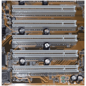
PCI was subsequently replaced by PCI Express (PCI-e) which is practically the only PCI slot you’ll see today.
PCI-X
PCI-X (where X stands for extended) comes with 32 or 64-bit slots that are designed to be backward compatible with 32-bit PCI cards. These cards are designed to run at 3.3 V. The higher voltage portion of the slot is beyond what the 32-bit 3.3 V card can reach.
PCI-e
Another variation of PCI is sometimes written as PCI-e (where e is for Express). PCI-e and PCI-X are not compatible with each other. When using PCI-Express, 16 lanes of communication are available and the physical size of the card will determine the number of lanes it may utilize. For example, an x16 slot will accommodate an x1 card
In the following image, you can see the PCI-e 16 slots: The first one is black and the second is blue. The slots can be used together for increased bandwidth.
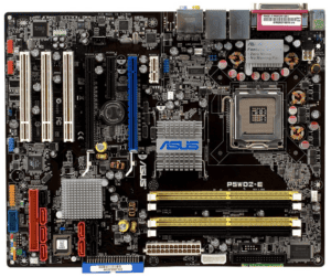
Also, the SATA connectors are visible in red with L shaped interior.
Mini-PCI / Mini-PCIe
USB is always an option when adding a wireless card. Here we’ll talk about internal expansion options: the Mini PCI slot and the Mini-PCIe slot. Here is how they compare. The Mini-PCI and the Mini-PCIe slot allow manufacturers to adjust laptop features to user needs without having to design a new laptop. The slot works the same way as in desktops, only on a much smaller scale. Accessible through a service panel, the Mini-PCIe slot is USB 3.0 compliant and can be used to increase storage capacity, add Bluetooth, or add/upgrade wireless capabilities. For example, a user with a decent laptop and 802.11 b/g/n/ac wireless only had to buy an 802.11g or 802.11ac card and swap it out if they wanted a wireless upgrade. This wireless upgrade required care and patience because while the card was easy to swap out, the internal antennae have tiny F-type connectors that take time and care to connect. Pictured here is a Mini-PCIe wireless card ready to be installed. Note the black slot and the gold antenna connectors. The card will be screwed into a secure position.
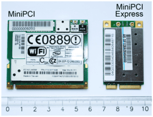
True computer portability was born in laptops with the introduction of the mini-PCI card. This card could be a modem or a wireless interface card. Improvements have followed but real untethered portability began with this standard.
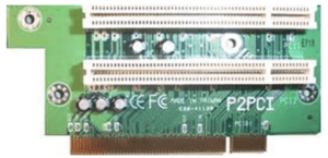
Riser cards
Space inside the PC has always been at a premium. One clever solution is to change the orientation of the installed expansion card. Instead of installing vertically in a single slot, the riser makes it possible to mount multiple cards horizontally from one vertical installation (see picture). The cards can vary in height but this does not have any impact on the case height. This type of arrangement can support up to four cards per slot. There is renewed interest with these cards due to the popularity of Home Theater PC units which need the capabilities of a full size PC with half the space.
Click here for our A+ Exam Simulator for exams 220-1101 & 220-1102
CPU Sockets
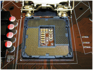
This section addresses CPU sockets, the processors they support, and the technologies they employ. The first thing you will notice is that there are many pin configurations and design variations. There are eleven individual socket types but these can be grouped into two main categories. The PGA (Pin Grid Array) type consists of a socket on the motherboard which is made up of a pattern of small receptors designed to only accept a particular chip’s pin pattern. Then there is the LGA (Land Grid Array) type which reverses the PGA design by putting the small fragile pins inside the socket where they have greater protection against bending and breakage. The LGA design also provides a more solid connection.
In consumer grade PCs you will have a single processor socket. In a physical machine supporting Windows server you will typically see 2 or 4 sockets. In virtual machines there can be up to 64 processors. You won’t do it, but you could!
Importantly don’t confuse the cores with the actual physical processors.
NOTE: Intel favors the LGA package while AMD offers a mix of LGA (TR4) and PGA chips (AM series and FM2). Intel and AMD processors use incompatible motherboards.
Although 32-bit processor architecture is present, today’s systems have moved to 64-bit architecture. Another thing to consider is that a new machine today will likely have its GPU (Graphics Processing Unit) integrated on the processor chip.
Notice how the LGA socket is configured to make optimal contact with an LGA processor. This is a bit of a hardware revolution compared to previous PGA designs which used pins on the processor chip to make the connection. These pins are not only fragile but get exposed to more incidental damage than those in the LGA design which uses the socket to help protect the pins. Be advised this does not mean that the PGA design is gone. LGA is where the technology is headed but PGA units exist in vast numbers.
Disable execute bit
Both Intel and AMD processors offer a hardware-based security feature that prevents application code from executing in specified memory areas. This feature is known by several names: Execute Disable Bit (EDB) and eXecute Disable (XD) by Intel and Enhanced Virus Protection (EVP) by AMD. This feature is generically called the NX bit (no-execute). CompTIA refers to this feature as the disable execute bit. Although it’s a processor feature, the disable execute bit must also be supported by the UEFI/BIOS and the operating system. When enabled, the processor can isolate certain memory areas and prevent the execution of malware, particularly those that produce buffer overflows.
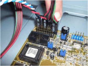
Front panel / USB connector
This is for the hundreds of thousands of technicians who spent their days crawling underneath desks to hook up speakers. We now have front panel connections for a variety of configurable connectors. This includes USB which allows for incredible ease of connectivity for a wide variety of devices. It’s safe to say your prayers (and mine) are answered.
Here are some of the options available for the front panel:
> USB
> Audio
> Power button
> Power light
> Drive activity lights
> Reset button
BIOS / UFEI settings
Here we will look at the PC’s BIOS (Basic Input Output System) and UEFI (Unified Extensible Firmware Interface) configuration from the CompTIA A+ 220-1101 exam perspective. Your knowledge of these technologies, old and new, holds the key to success on the A+ exam.
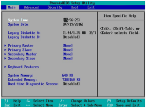
Take the System BIOS or UEFI as an example. Now, this is cool! It’s a GUI! Menu driven! And that is just looks. Now we stop and before the smart half of the class starts yelling, I’ll take care of this. If you are using UEFI you don’t have a UEFI BIOS. UEFI Is UEFI and BIOS is BIOS. Although they appear to perform similar functions, the similarities are superficial. For example, changing the boot drive is a common feature and easily configured for either firmware. The same is not true for configuring HDDs that are greater than 4 TB.
OK, we have identified the type of firmware involved and their roles but suppose you stumble on a working motherboard that has the components you need onboard! Fantastic news! All you have to do is ensure firmware compatibility. Depending on your equipment and its level of support, this can be as simple as pressing a button on the motherboard (UEFI) or as tough as assembling the whole machine and evaluating the results (BIOS). Refer to the documentation and choose your path.
In a BIOS-configured system, you will encounter a tab-based multilevel interface that is navigated using the keyboard only. Most BIOS have the following main tabs:
Main: Contains Main entries for system date and time. Shows the amount of installed memory.
Devices: Depending on your configuration, you may or may not have these choices. If you have the following items, this is where they will be: Serial Port Setup, USB Setup, ATA Drive Setup, Video Setup, Audio Setup, and Network Setup.
Advanced: Will contain settings for the primary CPU setup and manageability. Items such as Multiprocessing, Hyper-Threading, and Virtualization technologies will be controlled here.
Power: This section controls the system behavior after a power loss. Power saving settings are also stored here along with automatic cooling settings (if any).
Security Boot: This section contains the capability to lock down the system as necessary, from power on and administrative passwords to setting Secure Boot. Also listed here is the provision to allow or disallow BIOS flashing.
Exit: You can save your changes and exit or disregard them if you made a mistake.
Observing the BIOS configuration, you will notice settings for:
Boot sequence: Select the order in which device boot data is loaded. This could be anything from a USB stick, a CD-ROM, or a hard disk. For stronger security, disable USB boot.
Enabling and disabling devices: This controls which devices will be considered as acceptable when seeking boot data. Again, consider security factors when making these decisions.
Date/time: Current System Date/Time. A zero-day attack can be triggered by changing the date.
Clock speeds: Timings set for CPU and memory. Changing these could easily reduce system stability.
Fan Speeds: System cooling can be adjusted by automatically raising or lowering fan speeds based on the temperature of the processor and inside the case.
Virtualization support: Enable/disable hardware virtualization support
BIOS security: Enable/disable security settings including the Trusted Platform Module(TPM), and Hardware Security Module(HSM), passwords, lo-jack, and secure boot.
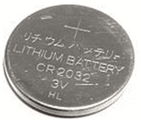
CMOS Battery
CMOS/UEFI settings (the System Configuration Information) are stored safely in the firmware. All of these essential settings are maintained by a small watch battery. When this battery is low or dead, signs of failure include the loss of the PC date and time and the loss of hard disks. Make certain that the configuration does not get lost or forgotten by keeping it electronically refreshed. Firmware is reasonably resistant to data loss but to be safe, it is periodically refreshed electronically using a tried and true 2032 battery. This battery model remains unchanged since 1985!
CPU features
When selecting your processor and motherboard, the key features you should be concerned with are the processor speed, the number of cores, and the amount of cache memory available. When calculating your processor speed, remember that if you have four 2GHz cores, the resultant speed is not additive. What you have is four cores capable of operating at 2.0 GHz simultaneously. Your processor with four 2 GHz cores does not equate to an 8 GHz processor.
A good look in the BIOS/UEFI will flesh out the rest of the information you need to satisfy this objective. On Intel motherboards, is hyperthreading enabled? You want hyperthreading to be active because this enables your processor to work on multiple tasks, smoothing out the operations and allowing several things to take place at once.
You also want to check your L1, L2, and L3 cache. These locations act as temporary holding areas for data that are in process but not complete. L1 is the fastest and usually the most expensive real estate on the machine. Generally, L1 cache is in multiples of 64k of fast memory on the processor chip. Following that will be the L2 cache. Sometimes L2 cache is on the chip but more often than not it’s on the motherboard. L3 cache, if present, will be on the motherboard. All of these relatively small storage areas save the PC from having to save and retrieve data from the system buses during routine operations.
Virtual technology
You will undoubtedly be tested on this topic. Virtualization enables you to run multiple instances of complete machines on a single hardware platform. This is a considerable resource-saving and quite a boost to productivity. Remember to check the BIOS/UEFI first. Enable either Intel VT or AMD-V depending on the processor. With virtualization enabled in BIOS, you can install as many virtual machines as you like! However, everything must be properly licensed. Once installed, you can’t tell the virtual machine from the original!
Expansion cards
Most of today’s PCs ship with video integrated into the motherboard. These solutions are more than sufficient for the average user. Very advanced users, such as graphic artists and extreme gamers, will order custom cards or manually upgrade their video components. Users will seek cards that have very high frame rates, as much fast memory as they can afford, and the fastest video interface attainable.
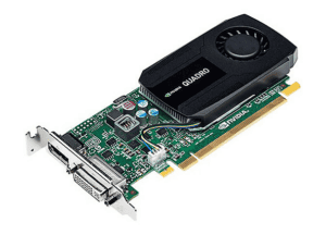
Here’s a card that fits the bill: PCI Express 2.0 x16 connection, good speed, fast memory, and lots of connectors. Adapters are usually used for other possible connections. These expansion cards can be used either as upgrades or as replacements for a failed motherboard component.
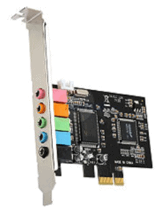
Sound cards
For most PCs, sound chips are embedded in the motherboards. If it is deficient, the sound will be one of the first PC shortcomings users will want to address. Usually, upgrades will entail a pair (or more) of speakers and a more powerful sound card to drive the speakers. Sound cards are usually internal devices that connect to a PCI expansion slot. A typical sound card is shown in the image below.
Network cards
There are two types of network cards: wired and wireless.
Wired network cards
First, we will look at the wired cards. These cards have either Fiber optic, Ethernet, or both. When your Ethernet card fails or if there is a good reason to upgrade, such as for a faster Ethernet switch, it’s time to look at your network specifications. Determine the best fit for the new or proposed network and select the card. Don’t buy it yet! Check your machine for free ports and make sure that they are compatible with your card choice.
Wireless network cards
The same holds true for wireless cards. Check the specs! Most of the time, you will end up adding an internal card but it is easy to find USB models of these cards. It’s easy to see that the wireless networking trend took off quickly and there were innumerable laptops and portables with Ethernet-only connections installed that needed wireless upgrades. The quickest and easiest solution to this condition was to develop a USB Wireless adapter. There! All fixed.
There are also numerous Wireless network cards available in PCI and PCI-e configurations as well as M.2.
USB cards
USB Cards provide additional or even faster USB connections to your PC. Available in several configurations (with internal and external ports), you can take a PC with USB 1.0 installed and add a USB 3.0 card. If the card has internal connections, you can also upgrade your hard disk. Ultimately, you will triple the throughput of your connected devices. If you have any need to upgrade, consider the USB option for ease of use.
eSATA cards
eSATA Cards are covered in objective 3.1, click here to go to Sub-Objective 3.1
That’s everything for sub-objective 3.4! Good luck on the test!
Click here to go back to the A+ Main Domain 3.0 Table of Content