A+ Exam Objective 3.1 Explain basic cable types, their features, and their purpose.
Click here to go back to the A+ Main Domain 3.0 Table of Content
Welcome to Exam Notes by CertBlaster! In this article, we will cover A+ 1101 sub-objective 3.1 “Explain cable types, their features, and their purpose”.
Sub-objective 3.1 rehashes some of the concepts covered in 2.1, although focusing here more on the cable types themselves such as their construction, bandwidth, and transmission limitations. Also discussed in this section are impediments to overall signal quality and safety concerns.
Beginning with fiber optics, there is a good deal of material you will be exposed to. An earlier section covered some of the connection types so apologies for any repetition. In this objective, the content will be more specification oriented and will cover questions such as “what is the maximum cable length?” and “what speeds does cable X support?” Err on the side of preparation. One question could be the difference between success and failure. Having said that…here we go!
Twisted Pair
Here, we look at the foundation and in many cases, the best solution, for your connections. Most of this is worth knowing for your general working knowledge base as well as for the test.
All of the following cable tables consist of some form of twisted pair cable. Cables can be broken into two classes: shielded twisted pair (STP) and unshielded twisted pair (UTP).
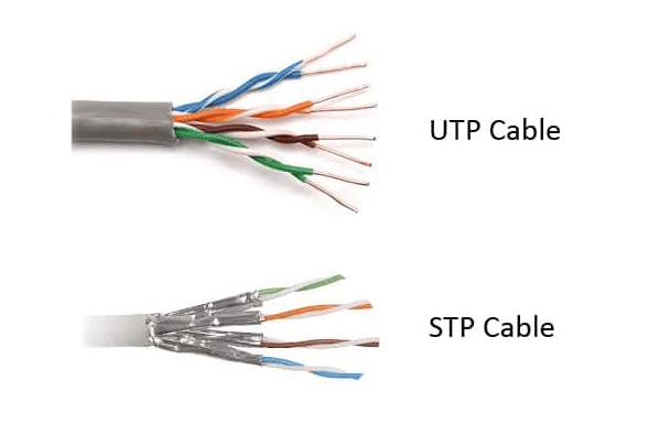
The difference between the two cable types is in the internal construction of the cable, specifically the amount of insulation or shielding surrounding each internal cable pair. Each internal pair is twisted using a specified number of twists per inch. This reduces the possibility of the pairs being parallel to each other and prevents crosstalk.
Types
CAT3 – Used in the early days, twisted pair implementations of this type use up to six wires or conductors. The most common use of CAT3 is the telephone which uses two pairs for each phone connection. This means the cable itself can support two phone lines.
CAT5 – Getting harder to find and no longer installed, this cable rating uses four pairs and can support up to 100Mbps transmission speeds with a maximum cable length of 100 meters (328 feet). You can get higher speeds in real-world applications but for the purpose of A+, remember the specification described here.
CAT5e – This cable is known as CAT5 Enhanced where the enhancement refers to reduced crosstalk. This doesn’t sound like a big deal until you look at the speed improvement. How does 10 times faster sound? CAT5e supports gigabit ethernet (1000Mbps)! This can be attributed to stricter attention being paid to the number of twists per inch in the pairs. Remember, your hardware has to support the speed. It’s not a magic cable. CAT5e supports 1Gbps with a maximum cable length of 90 meters (295 feet).
CAT6 – OK now we’re cooking! CAT6 supports 10Gbps at a frequency of 250 Mhz. These speeds can be attributed to a further reduction in crosstalk. While maintaining the same external RJ-45 form, the connector and cable are engineered to further isolate the cables from each other, resulting in the higher throughput.
The wires are arranged in the connector to allow a slight, yet significant separation compared with CAT5 wires, which run straight, horizontally, and adjacent to each other. As you know, parallel cables will practically guarantee crosstalk. The maximum length for a CAT6 is 90 meters with an additional 10 meters for a patch cable.
CAT6a – This cable grade improves the maximum 10Gbps bandwidth to 500MHz for the entire 100-meter run. Cat 6 will begin to reduce throughput after around 37 to 55 meters. This is accomplished using better insulation and tighter twisting of the internal wire pairs.
CAT6e – This enhancement increases the transmission frequency to 10Gbps MHz and restores the traditional segment length to 100 meters (328 feet). This is technically not a standard but CAT6e is recognized and observed.
CAT7 – This performance standard increases the transmission frequency to 600 MHz and provides a more reliable and durable cable than its predecessors. CAT7 wraps the entire insulated pair with an additional layer, wrapping the whole cable bundle to provide an additional layer of shielding.
Coaxial
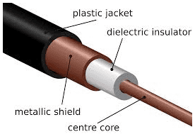
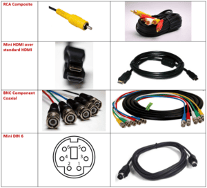
RG-6 (Radio Grade-6) cables have a variety of uses although they are used mainly in communication. Construction can vary somewhat by the manufacturer, but all RG-6 cables consist of a solid copper core encased in a plastic insulating sleeve, which is then covered by a wire mesh (sometimes foil) that insulates the cable from noise and provides grounding. All of this is contained inside a plastic jacket. On RG-6 and RG-59 cables, an F-type connector is used to terminate the connection. RG-6 is becoming the preferred cable type for cable television (CATV) installations.
RG-59 (Radio Grade-59) coaxial cables were once heavily used in CATV installations. The construction is identical to the RG-6 except the RG-59 uses a thinner core. The RG numbering system uses decreasing numbers to represent the size of the cores, making the RG-6 considerably thicker than the RG-59. Both cable types use F-type terminators.
This device will also split a cable. There are a few configurations available depending on your needs. However, as you know, there is always a caveat. If you are splitting RJ-45, there should be no decrease in performance since you have 8 wires available and the connection will use 4 wires (normal) for the first PC and the other 4 for the second. However, there will be a problem if you split an RG-6 or RG-59 coaxial (TV) connection. The splitter will split the speed evenly to each device. Depending on the amount of signal you have to begin with, one split generally isn’t a problem. However, your next split will take the 50% it receives and send 25% each to the downline devices. Image quality or performance issues may arise at this point.
Cable Jackets
Safety is your number one concern when running network cabling. This concerns not only the usual such as dangling cables or running too close to power lines, but also the materials you are using. The construction of the network cable you are running is something you may not consider, but when examining cables you will find that the outer sheath generally consists of one or two types of material, PVC (PolyVinylChloride) or Plenum grade. Incorrect usage of these two types could result in you having to rewire your entire installation. PVC is cheaper and is perfectly suitable for patch cables and exposed wiring, but once you run inside a dropped ceiling or any location that moves air, plenum-grade cabling is required by most states. PVC releases toxic fumes when ignited and it is easily combustible. Plenum cable is less flammable than PVC and is mandatory wherever ventilation is present. Plenum cable will be clearly marked.
Fiber Optic
Fiber optic transmissions use pulses of lights for signaling which are then sent over plastic or glass strands. The glass medium (fiber) is susceptible to breakage and signal loss if it is bent over a certain radius which is dependent on the thickness of the fiber. Fiber optic cable should never be coiled tightly.
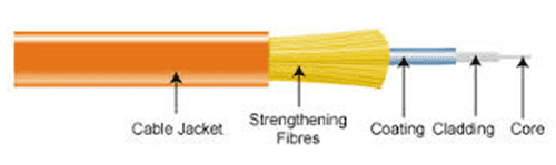
The fiber core is protected using a plastic sheath wrapped in synthetic strength fibers, which give the cable resistance to breakage. A plastic outer sheath completes the wire. If there is any concern about moisture seeping into the cable, a synthetic gel is used to fill any gaps and protect the fiber.
Connector Types
We will discuss the connector types covered in your objectives. The benefits of using Fiber optic cable versus copper are plentiful. Each connector can be configured to use single-mode or multimode. A few major benefits are shown below:
- Fiber has a broader bandwidth and is capable of handling more discrete channels at a higher speed. Fiber is immune to electromagnetic interference which causes signal degradation.
- Fiber suffers less signal loss (attenuation) over distance.
- Fiber cannot be “tapped” providing increased security over copper.
ST– The ST (Straight Tip) connector is one of the longstanding connector types. You will see this in the field and you should be able to recognize it on sight.
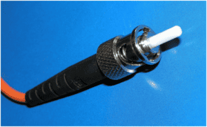
Helpful identification points to remember are the BNC type connector and the straight tip on the fiber.
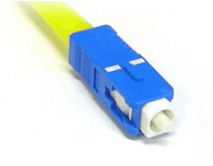
SC– The SC (Subscriber Connector) has also been in use for some time and is a very reliable and stable snap-in connector that offers low signal loss along with ease of use. You may sometimes see this connector referred to as a standard connector or a square connector because of its shape.
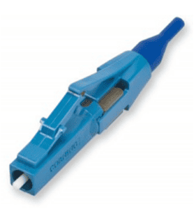
LC– The LC connector is a newer design relative to the others. You may see it referred to as a Local Connector, Lucent Connector, or even a Little Connector. The main advantage of this connector is its size. The LC connector is about half the size of the SC connector but otherwise completely comparable.
Click here for our A+ Exam Simulator for exams 220-1101 & 220-1102
Twisted Pair Connectors and Ethernet Wiring
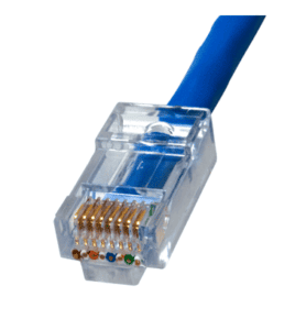
Now we’ll look at the copper network cable types. Once the most exhaustive connection method you would need to know for A+, the 802.3 series of cables are now being replaced by Fiber and Wireless. Nevertheless, 802.3 cables are still heavily used in the field with many networks running RJ-45 and wireless networks covering the same areas. We will now look at the two main twisted pair implementations: RJ-11 and RJ-45. Here is how the connectors compare.
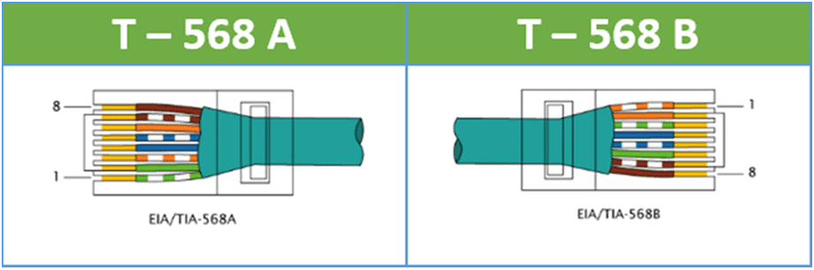
T – 568 A & B detail for CompTIA A+ 220-1101
Changes in network hardware have made it possible for this connector to reach speeds of 100Mbps. As the technology has advanced, even greater speeds can be attained by making enhancements to the internal configuration of the connector and the cable while leaving the original shape and size of the connector unchanged.
Coaxial
Another network cable option is Thinnet or the RG-58 variant.
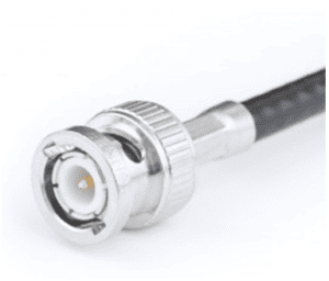
This 10BASE2 connector and cable were harder to manage than its 10BASET cousin. It used BNC connectors and a somewhat less manageable shielded copper core cable. RG-58 matched the 10Mbps speed and had a longer range, but it was difficult to implement the required bus topology and required a T connection at each host, along with termination at the cable ends, to prevent signal reflection.
F- Connector
Your objectives call for knowledge of the F-Type connector. This connector is not as much a network connector as it is a video connector. Your Home Media Center PC will require this connector in order to connect your cable or antenna system to it.
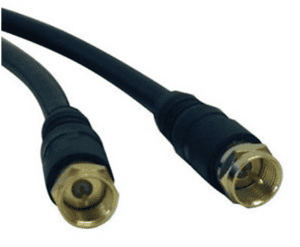
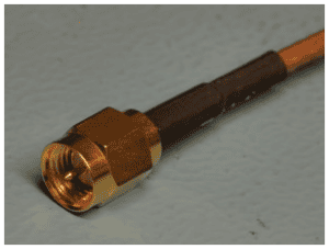
An RG-6 cable uses an F-type connector. It is similar to BNC, however the F-type connector screws onto the component, creating a connection where a failure point will most likely be the cable itself rather than at the connection point. The connection is strong and extremely unlikely to pull out.
Video Cables
We’ll discuss display connector types and cables. When using today’s PCs, the flat panel monitor is the way to go. When working in the field however, you will encounter a mix of older CRT (Cathode Ray Tube) monitors and TFT (Thin Film Transistor) flat panels which have a clear crisp resolution and deep rich colors. Most of the improvements you see in monitors today are the result of the greater number of pixels in the display combined with the tens of thousands of colors each individual pixel can produce. The color bit depth of the earliest monitors, or the number of colors the monitor can display, was 16 which was pretty good for 1984.
But now each individual pixel can produce over 16.5 million colors, making graphics look beautiful, realistic, and lifelike. So what does this have to do with connectors? When you think about it, the original monitors were monochromatic and as a result, didn’t have a heavy data load. These early monitors would only need to show mostly text and one color over black. As the display complexity increased, new interfaces were designed to support the increased amount of data.
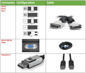
DVI D – I – A
We will discuss the connectors that you need to know. We’ll look first at the DVI connector and cable. This connector comes in three configurations and is capable of carrying digital signals, analog signals, or both depending on the type. DVI-D carries digital signals only, DVI-A carries analog signals only, and DVI-I carries digital and/or analog signals.
VGA (HD15), RCA, & BNC
The naming of the VGA connector has been updated to include HD-15 or DE-15, signifying the high-density capabilities of the connector and the cable. VGA is a 15-pin male connector although some older, high-end PCs used 5 BNC coaxial connectors, with each BNC cable carrying one color or synchronization signal, to improve picture quality. RCA cables have been used to carry analog component video.
DisplayPort & HDMI
The DisplayPort interface and cable are designed to replace the older VGA and DVI connections. An interesting note is that on a DisplayPort adapter, you will often find a VGA or DVI interface on it for flexibility.
The newest video interface introduced is HDMI (High Definition Multimedia Interface). This evolution of video controller is also capable of carrying device control information to compatible devices, allowing you to control your video player, game system, monitor, and multichannel audio amplifier through a single device via the HDMI connector. The HDMI connector and cable are available in three configurations, standard, mini HDMI, and micro HDMI. Often, you will find the standard HDMI connector on a PC or monitor and the mini HDMI or smaller micro connector on a camera or gaming system. The connection is designed to be compatible with updates to the HDMI protocol without changes to the connector itself. The original HDMI interface supported HDMI 1.0, shocked? But, the lessons learned with other connectors, like not being sure which connector will fit your device, lead developers to keep the connector intact and build in support for updates to the technology and cabling. This is comparable to Ethernet in that respect. So the cable you bought for your first HD TV probably won’t support your new 4K UHD TV, you need only use the cable that came with the new TV, easy peasy!
Thunderbolt
Currently, we have USB 3.0, running at 5Gbps, which is fast! However, faster still is the Thunderbolt card connection. For a time, Thunderbolt was only available to Mac users. Fortunately, Thunderbolt is available to all. Thunderbolt takes advantage of its low-latency/ high-bandwidth design to achieve theoretical speeds of 20 Gb/sec, through two channels, although your mileage may vary. This technology has been crucial to the 4K/UHD revolution. The 4K/2K maximum resolution is 4096 x 2160 and is the maximum resolution of 4K Ultra HD. 4K Ultra HD should be seen to be fully appreciated as it is similar to your first HD TV experience, but times FOUR!!!
Display cable types
For the A+ test, you will be expected to know about the following cable types. You will also need to be able to identify the pre-USB mouse and keyboard connectors that use the mini Din 6-pin connector.
PC connector types and cables
Multipurpose cables
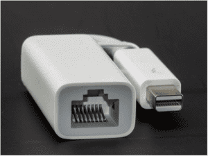
A dongle is a connector that allows a peripheral device to connect with other devices. An example is an RJ-45 dongle that has PC-compatible connectors. Shown below is an RJ-45-to-Thunderbolt dongle that we’ll discuss later. It might be a little hard to make out but notice the small Thunderbolt logo on top of the smaller connector to the PC.
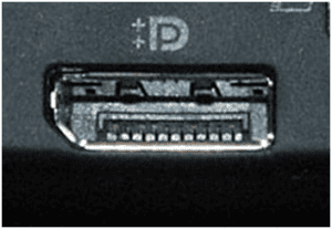
When Wi-Fi was still a novelty for the average consumer, Wi-Fi dongles permitted Wi-Fi access to devices that didn’t originally have it. When 802.11b devices needed to be upgraded to 802.11g or 802.11n, Wi-Fi dongles were used to accomplish this. Bluetooth adaptation is another area where rather than buying a new laptop, a user can simply add a Bluetooth dongle. For Mac users, there is a USB alternative through DisplayPort. Here is a full-size look at a laptop’s DisplayPort.
Technically, the Mini-DisplayPort is still a dongle in the general sense of the term. The DisplayPort interface allows ultra-high resolution, 3D, and data connectivity and 8 high-resolution audio channels. Only your dog will notice the high end of the 24 bit 192 kHz output, but it will be there.
During the lifespan of DisplayPort, another high-resolution technology called Thunderbolt was released. To avoid confusion, Thunderbolt connectors were designed to support all the features of DisplayPort. When connected, Thunderbolt has the advantage of chaining Thunderbolt devices together through a single interface. The Thunderbolt data transfer rate exceeds USB 3.0 and FireWire 800. The Thunderbolt (PCI-Express) signaling uses two dedicated channels which provide isolation for the send and receive signals. While being physically identical to the DisplayPort, the Thunderbolt connector and port can be identified by the Thunderbolt logo present on both the connector and the port.
Device cables and connectors
SATA & eSATA connectors
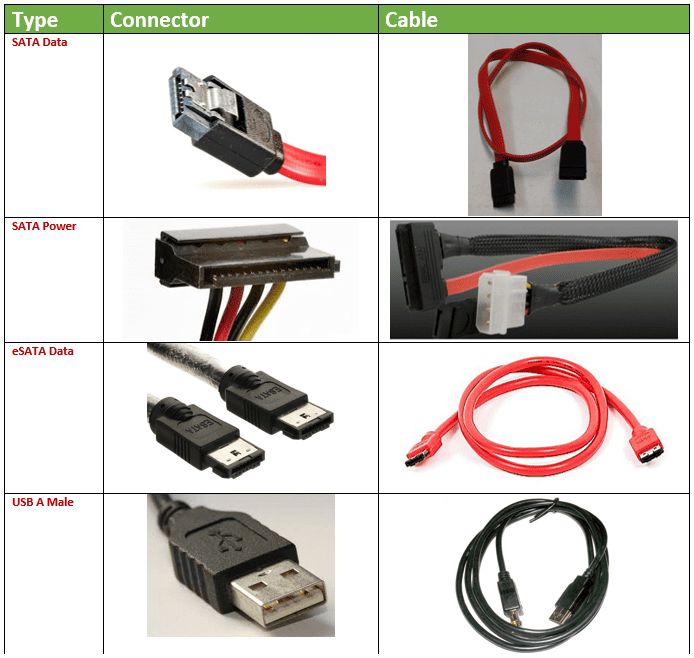
This connection uses Serial Advanced Technology Attachment (SATA) for internal drive connections such as hard disks and optical drives. SATA is the replacement for Parallel ATA (PATA) which was the preceding primary drive connection method. Because of its flexibility, the SATA interface can connect externally to the machine using an eSATA port. In the table, you can see the internal SATA data and power connectors. Many SATA devices ship with a MOLEX-to-SATA adapter cable for power. eSATA connects external devices. You can distinguish SATA from eSATA by noting the L-shaped SATA connector. The eSATA connector has a straight rectangular interface and an external rib on each side of the plug which prevents improper insertion.
USB Connectors
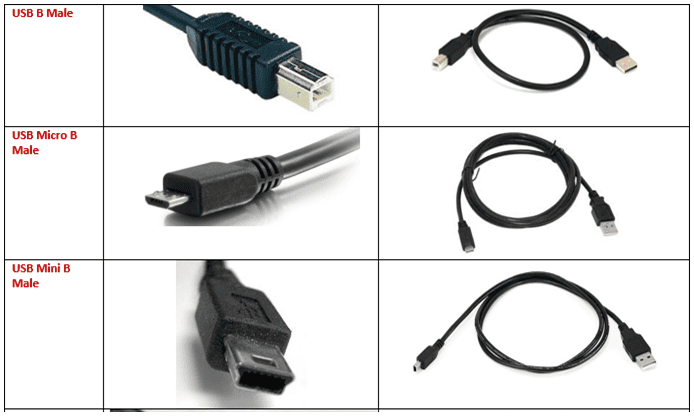
Next, we see the USB and the various cable configurations. First is the USB A Male connector which is the machine end of a standard USB 1.0-to-2.0 cable. The USB 3.0 cable end will be identical in size and shape but is colored blue to differentiate it from the older versions. USB extension cables are available and will have a USB A Male connector on one end and a USB A Female on the other end.
On a standard USB 1.0-to-2.0 cable, the devices will connect using a USB B Male connector. As the selection of USB-connectable devices grew, these devices also became smaller which called for a new, smaller connection type. For example, the USB A connector ended up being larger than the new cell phones and tablets that it needed to connect to. These smaller connectors started with the Mini A connection which has been deprecated in favor of the Micro connection. The Micro connection is half the height of the Mini, making the Micro connectors 1.8mm high.
Table 1: Device cables and connectors
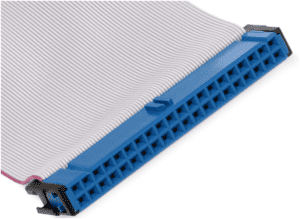
Note: The IDE connector (aka PATA) is a legacy hard disk connector. Newer PCs will not have this connection type. If you are dealing with an older machine, you will need to recognize the cable as shown below.
Adapters and converters
USB A to USB B & USB to Ethernet
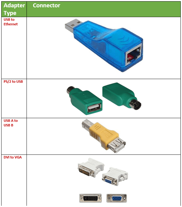
In this section, we will look at the adapters and converters that can be used to modify the connection type from one to another. You will find two basic configurations: one single adapter where each end has the desired connector and the other configuration where both connections are attached to a short length of cable (a dongle).
Adapters and converters are extremely useful, with USB-type adapters and converters being the most common. You can find a USB adapter or converter to modify practically anything. Consider a one-piece USB adapter that converts an RJ-45 Ethernet cable to USB. A little device like this can save you from having to replace the hardware in a desktop or can help you add functionality to a machine that does not have an Ethernet adapter. One of the earliest adapters of this type was the PS/2-to-USB adapter. This came with new (at the time) mice, allowing you to connect a USB mouse via your PS/2 connection. During this time, USB ports were uncommon and if you had USB capability on your machine, you probably only had two ports.
If you need to change the “gender” of a USB port, it is possible using the USB B-to-A Adapter which is shown in the table below. This helps if you need to connect to a USB B device and, like most of us, have a cable collection consisting of only USB A cables. You will be all set with no loss in capability or performance! This is also indispensable if you need to add length to an existing cable.
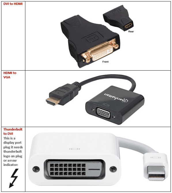
DVI to HDMI and to VGA & Thunderbolt to DVI
Now we’ll move on to video converters and adapters. There is no shortage of video converters and adapters although your only real concern is to not send digital signals over an analog connection. This is not really an issue for the most part as the signal is converted before transmission and these adapters are not manufactured. This is a good way to differentiate between these components.
An adapter is a component that basically rewires the connection from one pin configuration and shape to the desired pinout and shape. A converter adapts the configuration AND modifies the electrical properties of the signal being carried to the desired format.
For example, DVI-to-VGA is an area where the digital versus analog issue will present itself. VGA uses analog signaling whereas DVI is capable of either. You have to be careful. The VGA (or DB-15) interface is an analog-only connection type and digital signals are not handled. Make sure you have a DVI-A connection which is analog only or as a second choice, DVI-I which is integrated to carry either digital or analog. In the latter case, look at to the graphics adapter settings to be sure. That aside, all you need is the little adapter shown below. There are also digital-to-analog and vice-versa converters available should you find yourself stuck.
Next, let’s consider DVI to HDMI. These data formats are compatible although DVI is unable to carry the audio signal.
Next, let’s consider HDMI to VGA. Since we’ve established that VGA is analog and that HDMI is digital, a converter is needed as you can see by the small brick at the cable end of the image. However, it gets the job done!
The last entry in our list of goodies is the Thunderbolt-to-DVI adapter. This is an interesting case because of the multiport compatibility between the Thunderbolt interface and the mini DisplayPort (mDP). These two interfaces are very closely designed and are almost, but not completely, interchangeable. Thunderbolt uses the same connector as the mDP and for the purposes of this comparison, the differences are insignificant. Since the DVI connection and the Thunderbolt/mDP connection are both digital, only an adapter is necessary. No converter is needed.
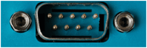
DB9
And lastly for this section we have the venerable DB9 connector. it has been known by various names over the years, most commonly the Serial port. It was used to connect the mouse. It one of the original (literally) input/outout ports. It was one of the only ways to get data on or off a PC. Its technical specification is RS-232. It served as your PC’s method of communication. The only other way to get data on or off of your machine was the floppy disk.
As the Internet was being born the serial port carried the signal! Your grandparents used an analog modem attached to an analog telephone line to dial a phone number and after some screeches, squeals and honks, negotiate a connection to another PC somewhere in the world to exchange data. You may have to look up some terms like floppy disk, analog modem analog telephone line. It’s a far cry from clicking a browser icon. All of this was before even the GUI was common. It still exists because it will be the only way two devices can communicate without a network.
That’s everything for objective 3.1 and your little history lesson! Good luck with the test.
Click here to go back to the A+ Main Domain 3.0 Table of Content