The type of service you use to connect to the internet is classified next. The connection type determines your bandwidth and connection requirements.
A legacy network type is Dial-up networking it is the original copper-based analog method of connecting PCs using the Public Switched Telephone Network (PSTN). You may also see this called the Plain Old Telephone System (POTS), the terms are interchangeable and describe circuit-switched point to point connections between devices. Since the system was designed to handle voice (analog) communications, the PC to PC connection required modulation to convert the digital PC signal to analog for transmission. On the receiving end, the signal was demodulated back to digital. The device used for this modulation/demodulation is called a Modem. You can expect connection speeds up to 56kbps. You may still see modems on devices that send and receive Faxes. A standard Fax machine requires an analog connection and can not be used with a VoIP line. Here is a look at the dial-up internal PCI modem:

PCI Modem
Another legacy copper-based technology, ISDN uses the PSTN for its connections breaking the transmission into two channel types, the circuit-switched B channel which carried voice data and video, and the packet-switched D channel which carried connection information like initiation and termination, conference calling and caller ID. In its basic configuration, an ISDN connection supported two B channels and one D channel. This is known as the BRI (Basic Rate Interface). Multiple B channels are supported but only a single D channel. Of the two B channels provided in BRI, they can be combined to provide 128 kbps for data, when the telephone is used one of the B channels is allocated to carry the voice signal. In the configuration known as PRI (Primary Rate Interface) Up to 23 B channels of 64kbps each are supported with one 64kbp D channel. ISDN signals have a limited range before a repeater is needed.
DSL (Digital Subscriber Line) is another copper-based connection method capable of using the PSTN to support multiple voice and data channels. DSL can support multiple channels of voice and data at very high speeds. In a best-case scenario, it can be comparable to T1 or cable broadband connections. Your DSL throughput is dependent on your proximity to your telephone company’s Central Office (CO). The DSL signal suffers range limitations like ISDN. As a rule, the closer you are to the CO the greater your throughput. There are several varieties of DSL; they are referred to collectively as xDSL with x being the variable. Here are the most common implementations:
This is the most common DSL implementation. It offers greater download speeds than the upload speed.
Here the upload and download speeds are the same. Maxing out at roughly 2 Mbps in each direction.
This will be your fastest DSL implementation. You may see it called “very high bit rate” DSL. This is an asymmetric method with upload speeds approaching 50-60 Mbps. This again is relative to the distance to your CO.
Cable companies have been promoting Internet services since the late 1990s. Cable broadband uses the coaxial copper wiring used to carry TV signals inserts a cable modem to use the available bandwidth for internet access. This is an asymmetrical connection that can support downloads of up to 10 Gbps with the latest modems. This is a viable competitor to fiber-optic internet service providers with even the cable companies using fiber-optic backbones to provide more throughput. This implementation is called HFC (hybrid fiber-coaxial). -An enviable cable broadband speed result is shown below.
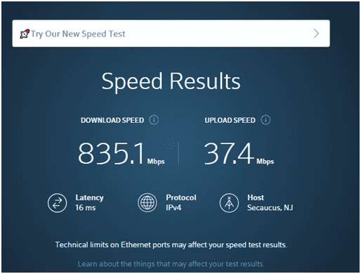
Cable Broadband Speed Test
In contrast to the technologies listed so far only the T-carrier, E-carrier in Europe, technology provides a high-speed dedicated logical circuit that is used exclusively by the customer. Developed in the 1970s the T-carrier system offered businesses dedicated always available connectivity. To use the service the customer leases the lines according to their bandwidth needs. The cost of the service varies and is dependent on the distance between the provider and the subscriber and the subscriber’s line rate requirements. The T carrier system uses TDM (time-division multiplexing) to allow a single T1 circuit to carry 24 channels with a throughput of 64 Kbps each. A T3 circuit carries 28 channels at 64Kbps each.
In some cases, multiple T1 lines may be more cost-efficient than a single T3. The chart below compares the primary U.S. And European service levels.
| Network | Channels | Line Rate |
| T1 | 24 channels at 64 kbps each | 1.544 Mbps |
| E1 | 32 channels at 64 kbps each | 2.048 Mbps |
| T3 | 28 T1 circuits 672 channels | 44.736 Mbps |
| E3 | 16 E1 circuits 512 channels | 34.368 Mbps |
T and E Carrier Comparison
The SONET (Synchronous Optical Network) signaling technique uses fiber-optic cabling to provide fault-tolerant high-bandwidth WAN connections. SONET uses multiplexing to combine multiple T1 lines. SONET became internationally deployable when the SDH (Synchronous Digital Hierarchy) was implemented. The synchronous data transmission depends on all devices conforming to the timing scheme maintained by a clock that can be checked by individual nodes. When measuring the data rates the OC (Optical Carrier) method is used.
| SONET | Line Rate |
| OC-3 | 155.52 Mbps |
| OC-12 | 622.08 Mbps |
| OC-48 | 2.49 Gbps |
| OC-192 | 9.95 Gbps |
Optical Carrier Data Rates
You may also see Metropolitan Ethernet labeled Metro Ethernet. Both terms can be used to describe the technology used to ensure that cities and municipalities were able to communicate during emergencies that interrupted traditional Ethernet services. The Metro Ethernet has since evolved, through the use of the T-carrier system, into what we now call Carrier-Ethernet Transport (CET). CET establishes a virtual tunnel that uses a predetermined path. The Metro Ethernet has the advantages of familiarity for LAN technicians, cost savings using existing Ethernet hardware and scalability by nature of easily expandable Ethernet configurations.
There are close to 5,000 satellites currently orbiting the Earth! They serve various purposes from observation to GPS. Of particular interest to us are the nearly 800 communication satellites. The communication satellites make it possible for us to communicate with nearly every part of the globe delivering data, voice or video. This is made possible by placing the satellites in a geosynchronous orbit, meaning that when viewed from Earth the satellites appear to be stationary. Some communication satellites maintain a geosynchronous orbit above the equator and are called geostationary. This stationary technique allows accurate transmissions between the Earth and the other geosynchronous satellites. Satellite communication relies on line of sight transmission and is subject to physical obstructions like thick storm clouds, a condition known as rain fade. It also has higher latency than other WAN technologies since the signal is transmitted thousands of miles to the satellite and then thousands of miles back down.
From the first telegraph line to today’s high-speed networks, copper cabling has been fundamental. While it is being displaced in WANs you will still find copper in last mile implementations like coaxial Broadband, DSL, and the T1-T3 local loop. Ethernet and wired phone systems will also be copper. Copper is a low-cost, low-maintenance installation
Since fiber-optic cabling transmits light it offers very high-speed connections that can travel long distances. Fiber offers very high data rates and is the backbone of SONET.
Fiber-optic cabling is quickly challenging some of the traditional copper connections. You will see fiber-to-copper deployments. Some service providers are even offering fiber-to-premise installations that will bring the full features right to your home or office.
The best example of a wireless WAN is the cellular network. Today’s smart devices can access the internet, make calls and send data almost seamlessly. This is important to business travelers and field technicians who may not have alternative options. We say almost seamlessly because your connection quality is relative to your distance from the cell tower. Most cell tower coverage areas overlap and hand the signal off from one tower to another when you are in motion.
Multiprotocol Label Switching (MPLS) is a connection-oriented method that is used to route data between nodes on a network over the most efficient route. It allows Layer 3 protocols to operate at Layer 2 It allows packet-switched data to travel over circuit-switched connections. SONET and Metro Ethernet networks use MPLS. The first router to encounter MPLS traffic adds labels called a shim which is placed between Layer 2 and Layer 3 information. Next, a Layer 2 Protocol header is added.
A group of Layer 2 protocols were defined in the 1980s as frame relay, a fast packet-switched network for ISDN connections. Frame relay is connection-oriented. It can be used for virtual circuits. Frame relay data is separated into frames of variable length and are relayed from node to node without any processing. A PVC is established by routers and the frames are tagged with a DLCI (data-link connection identifier) to allow routers to quickly forward the packet without inspection.
Asynchronous Transfer Mode (ATM) is considered Layer 2 WAN technology. Its protocols can extend to Layers 1 and Layer 3. It can employ multiplexing techniques and network access. Since it is asynchronous it is not bound to the timing restrictions of SONET and can transmit data randomly as needed. ATM uses a fixed size 53-byte cell to transmit data. This cell consists of 48-bytes of data plus a 5-byte header and provides predictable efficient network communication. ATM uses virtual circuits using the optimal path determined before the transmission.
The Point-to-Point Protocol (PPP) directly connects two endpoints on a WAN. PPP uses headers and trailers to encapsulate packets into frames using 8 to 10 bytes of additional data. Along with establishing the connection, PPP supports authentication using protocols like EAP or MS-CHAPv2.
PPP over Ethernet (PPPoE) denotes the use of PPP on an Ethernet network.
To support both client-to-site and site-to-site on an enterprise-wide WAN the Dynamic Multipoint VPN (DMVPN) was developed. This technique allows VPN tunnels to be created dynamically on demand. This reduces the need for static site- to site tunnels.
Where there is an existing broadband connection SIP (Session Initiation Protocol) trunking can use VoIP to create virtual circuits supporting multiple VoIP calls using all available bandwidth. SIP trunking is an economical alternative to the T1 PRI.
It is important to know where the provider’s responsibilities end and the customer’s begins. This point is called the demarc (demarcation point). Today’s demarks will be a NID (Network Interface Device) or NIU (Network Interface Unit) placed on the outside of your building or directly inside the premise. The provider is responsible for the delivery of the signal to the demarc and its operation while the customer is responsible for the signal distribution from that point. This is a good place to start troubleshooting network issues.
Often you will find that the demarc device is a smart jack capable of monitoring the connection for data errors and reporting them to the carrier. The smart jack can also be checked by the technician by monitoring the status and activity LEDs.
The CSU (channel service unit) is usually a stand-alone device that is placed between the NID and the first internal router. It serves as a digital signal termination point and uses error correction and line monitoring to ensure data integrity. The DSU (data service unit), built-in with the CSU, converts the incoming frames from the T-carrier into Ethernet frames for the network. The process is reversed for transmissions. The evolution of these devices has made the CSU/DSU available as an add-on card in a router lowering cost and maintenance concerns.
Click here to go back to the table of content for Network+ Main Domain 2.0
That’s all for 2.5 and the 2.0 Domain. See you in Domain 3.0!