Network+ N10-007 ExamNotes for sub-objective 1.3 Explain the concepts and characteristics of routing and switching – Part 1 of 3
In order to understand routing and switching you should be comfortable with the logical and physical aspects of the networks, you will encounter along with the behavior of the devices that control their traffic.
CompTIA Exam Sub-objective 1.3: “Explain the concepts and characteristics of routing and switching.”
Properties of network traffic
Broadcast domains – CSMA/CD – CSMA/CA – Collision domains – Protocol data units – MTU – Broadcast – Multicast – Unicast.
Segmentation and interface properties
VLANs – Trunking (802.1q) – Tagging and untagging ports – Port mirroring – Switching loops/spanning tree – PoE and PoE+ (802.3af, 802.3at) – DMZ – MAC address table – ARP table.
For the rest of the 1.3 exam objectives go to Part 2 and/or Part 3.
Click here to go back to the Network+ ExamNotes Table of Content
Properties of network traffic
– Broadcast domains
A broadcast domain can be described as a LAN using switches as its boundaries. Switches can deliver port to port transmissions between nodes reducing overall network congestion. The switch will determine the destination of the traffic and whether or not it should be forwarded to a router.
A broadcast domain is connected to the router through switches. When nodes are connected to a hub a collision domain is created. Remember a hub delivers all traffic to all connected nodes creating the high probability of simultaneous transmissions. In a data collision, all packets are dropped and a resend is required. The resend or retransmission has the same probability of success as the initial one. This calls for signal control over the media.
Media Access Control methods such as Carrier Sense Multiple Access (CSMA) were developed to alleviate the problem. Here the transmitting NIC senses or listens for traffic on the carrier media and waits for it to clear. Multiple access represents multiple nodes contending for time on the media. This approach is most applicable to 802.3 Ethernet with legacy hardware.
– CSMA/CD
Since all nodes in a collision domain are competing for access to the transmission media Carrier Sense Multiple Access (CSMA) methods are necessary. This is especially true on Ethernet connections. Carrier Sense refers to the transmitting NIC listening on the media for traffic before transmitting. Multiple Access refers to multiple nodes using the same media.
There are two methods of CSMA. First, we’ll look at CSMA with Collision Detection (CSMA/CD). In this method, the NIC transmits when the media is clear and monitors the transmission. If a collision is detected it can send a jam signal to all nodes that the media is in use then continue the transmission.
– CSMA/CA
CSMA with Collision Avoidance (CSMA/CA) takes a different approach when dealing with collisions. Here once the media is clear, the transmitting node signals the whole collision domain that it will transmit and the other nodes back off their transmissions.
– Collision domains
See Broadcast domains.
– Protocol Data Units
A Protocol Data Unit (PDU) is a message or group of bits containing data and addressing information. As the PDU id is processed through the OSI model, each layer adds or removes formatting information to prepare the payload for the next Layer. As it moves through the layers it will be referred to by a different term. Here is how those terms break down by layer:
OSI Model |
Term |
|
| Layer 1 | Physical layer | Transmission or bit |
| Layer 2 | Data Link Layer | Frame |
| Layer 3 | Network Layer | Packet |
| Layer 4 | Transport layer | TCP segment or UDP datagram |
| Layer 5
Layer 6 Layer 7 |
Session layer
Presentation layer Application layer |
Payload |
– MTU
Essentially the MTU (Maximum Transmission Unit) represents the largest size supported by the Network layer (Layer 2) routers. The standard size is 1500 bytes. There are exceptions that would allow larger frames. For example, VLAN frames have an extra four bytes and a jumbo frame, used in special-purpose networks, which can be up to 9198 bytes.
– Unicast
Unicast transmission is a typical host to host transmission where the message is intended for a single destination.
– Broadcast
A Broadcast transmission will be sent to every node on the network or segment in a broadcast domain. It is generally used for address resolution when the destination host is not known. Broadcast messages can be sent by a new connection to announce its presence. ARP requests are broadcasted. Router updates also rely on broadcasts.
– Multicast
Multicast refers to transmissions that are sent to multiple nodes simultaneously. A good example of this is multimedia streaming. Here each intended recipient is configured to receive this traffic.
Segmentation and interface properties
Network segmentation improves performance and security within a broadcast domain. It breaks the domain into more efficient groupings. This can be done using subnets or using VLANs (virtual LANs). We’ll look at these methods next.
– VLANs
VLANS are created using the ports on a Layer 2 switch. The method allows traffic to be directed either to a router or to or a virtual broadcast domain. This allows larger broadcast domains and multiple virtual LANs to be created.
– Trunking (802.1q)
Trunking is the term used for using a switch to support multiple VLANs. On a switch, a trunk is a single connection that supports multiple virtual connections. An 802.1q VLAN tag is placed in an Ethernet frame following the addressing fields.
– Tagging and untagging ports
Each port on a switch can be configured independently. This allows for ports to be grouped together and assigned to VLANs. When using a trunking protocol the 802.1q tag is read by routers or switches in the path to the destination. When the final switch is reached it removes the tag.
– Port mirroring
Port mirroring is also known as SPAN (Switch Port Analyzer). This technique sends a copy of all traffic on a port to a network security device such as a NIDS. The security device will monitor the traffic for anomalies and report them.
– Switching loops/spanning tree
In networks using multiple switches, it is possible for a failed broadcast transmission to be retransmitted by all the switches on the network (loop) until they eventually flood the network. This problem is addressed by the Spanning Tree Protocol (STP). STP identifies potential switching loops and blocks them. In Network+ N10-007 sub-objective 4.6 we’ll look at STP communication in greater detail. For now, we can say that STP uses Bridge Protocol Data Units (BPDU).
– PoE and PoE+ (802.3af, 802.3at)
IEEE standards 802.3af (PoE) and 802.3at (PoE+) define how electrical power can be transmitted over Ethernet cabling. (PoE) This is highly beneficial in networks that have devices that cannot be powered by the traditional electrical grid. Utilizing unused cable pairs in Cat5 or better cabling PoE delivers 15.4 watts of electricity to devices while PoE+ delivers 25.5 W. Two devices are specified by the PoE standard: The Power Supply Equipment (PSE) and the Powered Devices (PDs)
– DMZ
A Demilitarized Zone (DMZ) is a network space between your network’s internal and external firewalls. Let’s say that you have an external DNS server that you wish to be accessible to the internet. The firewall protecting your external DNS server will allow for a more relaxed configuration than the hardened firewall protecting your internal DNS server.
– MAC address table
The network switches we use maintain a list of MAC addresses. This list is comprised of Mac addresses it knows and those that are updated from other switches. A good example is where inbound communication is intended for a MAC address that is on your network and known to the switch. The source MAC address of this communication will be added to your switch’s MAC address table and the source would be known. The MAC address table is also used to drop incoming packets that are not intended for known internal devices.
– ARP table
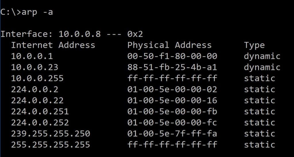
The ARP (Address Resolution Protocol) is responsible for mapping IP addresses to MAC addresses in IPv4. ARP maintains a database of the MAC addresses on the local network and the corresponding IP address. This is known as the ARP table. This table is built by initially broadcasting requests to IP addresses in its range. The devices respond with their physical (MAC) address.
The ARP table contains two types of entries, static and dynamic. Static addresses are entered manually. Dynamic addresses are added when an internal host requests an address that is not in the ARP table. Once located that new IP to Mac address mapping will be added to the table. You can view the ARP table on a Windows machine by entering arp –a at the command prompt.
Click here to go back to the Network+ ExamNotes Table of Content

6 thoughts on “Network plus N10-007 ExamNotes sub-objective 1.3 routing and switching – Part 1 of 3”
You are most welcome!
Under the section of Protocol Data Units, the word “congaing” is used. I believe it should be “containing”?
Thank you, Kenny! This is corrected and live.
Just want to say that I really appreciate this website! I am applying for an entry-level position to be trained as a network analyst, and I am using this website to study for my Net+ cert! Thanks again!
Cheers!
Thank you Stache! We are excited you like it and grateful you shared. The whole CertBlaster team wishes you all the best in your quest for Network+ certification!
Well, in a broadcast domain the frame is sent to all nodes in the subnet. I don’t understand “LAN using switches as its boundaries” because honestly, the router is the boundary and the NIC in the router is also in the broadcast domain. All interconnected switches are in the same broadcast domain unless you are using VLANs to create virtual boundaries/subnets.