Welcome to Exam Notes by CertBlaster! This our free study guide Network Plus 5.3. In this edition, we will cover the topics in exam objective 5.3 “Given a scenario, troubleshoot common wired connectivity and performance issues.” We will cover the conditions that impact network performance and connectivity.
As a signal travels away from its transmission point it becomes weaker. This condition impacts wired and wireless signals. In addition to distance, factors like noise and cable imperfections contribute to attenuation. On the network switches and repeaters refresh the signal to its original strength before passing it along.
The time it takes for a signal to travel from its source to the destination is called latency. The latency is measured in milliseconds (ms).
During network communication, the sequence of the packets can be delayed and arrive out of sequence. This is called jitter or PDV (packet delay variation). The signal path and latency both contribute to jitter. Typically jitter only causes slight delays in normal network traffic as lost packets are retransmitted. Jitter is most noticeable in VoIP, video streaming and gaming. The solution is a small buffer to allow steady data flow.
Ethernet cables consist of eight wires wrapped into a single cable. With each cable capable of generating EMI. The wires are separated into pairs and twisted to prevent the wires to run in parallel and reduce interference or crosstalk. Crosstalk can be found at the cable ends where the wires run parallel into the connector. Interference that occurs at the transmitting end is called NEXT (near-end crosstalk) and at the receiving end, it is FEXT (far-end crosstalk).
All electrical devices generate electromagnetic interference (EMI) to some degree. Our networks can usually mitigate this interference with a strong signal. Problems occur when our network cabling is too close to powerful electrical devices like generators and motors. Also consider the proximity of cabling to power lines, fluorescent lights, and microwave ovens. Use STP cable or reroute the cable to eliminate/reduce the impact.
Cables that are run through walls or overhead are not usually subject to damage. However, you will find some cabling run under a floor mat or rug. This subjects the cable to foot traffic that can eventually damage the cable. Some cables can be pinched between the desk and a wall which will cause damage over time.
An open circuit is one that is damaged or is not physically connected. A short circuit occurs when two exposed cables touch creating a useless and possibly harmful circuit. A multimeter or a cable continuity tester can help you quickly diagnose these conditions. If the problem is inside the cable sheath you can use a TDR to locate the problem.
A cable tester can detect improperly terminated cables.
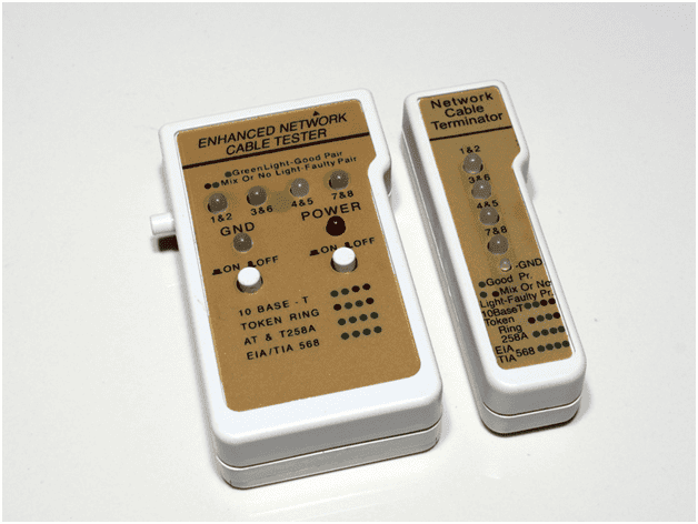
Network cable tester
RJ-45 uses four twisted pairs of wire configured to reduce crosstalk and other cable related problems. What you need to know here is how the RJ-45 connectors are wired. There are two dominant wiring pinouts T-568A and T-568B.

T – 568 A & B detail
Changes in other network hardware made it possible for this connector to reach speeds of 100Mbps. As the technology advanced even greater speeds could be attained by making enhancements to the internal configuration of the connector and cable while leaving the original shape and size of the connector unchanged. When a cable is terminated with the same T-568 standard at both ends it is called a straight-through cable or patch cord. The straight-through cable is the most commonly used to connect devices to the network. When a cable is terminated to the T-568A standard on one end and T-568B on the other it is called a crossover cable. This cable reverses the transmitting (TX) and receiving (RX) pairs to allow two devices to communicate directly without network support.
The Ethernet cabling used to connect to the network are all rated according to the specification they support. It is important to look at the cable sheath for the specification it supports. A Cat5 cable on a Cat 6 network will not perform as expected.
When diagnosing a connection issue always check the network adapter the connection LED status indicators You can use a loopback plug to diagnose a bad port or failed adapter. It is possible that the port has bent pins creating intermittent connections or no connection at all.
Transceiver/Duplex/speed mismatch
Using a switch that supports modular interfaces allows you to tailor the number and type of connections your network requires. Many switches support hot-swapping each modular interface allowing easy upgrades. Existing Ethernet interfaces can be upgraded to fiber using transceivers. Each connection will use matched pairs of transceivers that support the same speed and duplexing capabilities to avoid Transceiver, speed and duplex mismatches. These conditions contribute to network bottlenecks.
A switch will be configured support one preconfigured default VLAN containing all switch ports which cannot be renamed or deleted and additional native VLAN(s) that should be renamed for security. When configuring native VLANS remember that both ends must match the VLAN assignment or a VLAN mismatch will occur.
Click here to go back to the Network+ Main Table of Content
That’s it for objective 5.3. We hope you enjoyed the free study guide Network Plus 5.3See you at 5.4. Good luck on the test!